Preparing for Sharpening
It is important that you are familiar with all the controls of your XR28™ Sharpener and that it is set correctly for the sharpening cycle.
Sharpening Head
Understanding your controls.
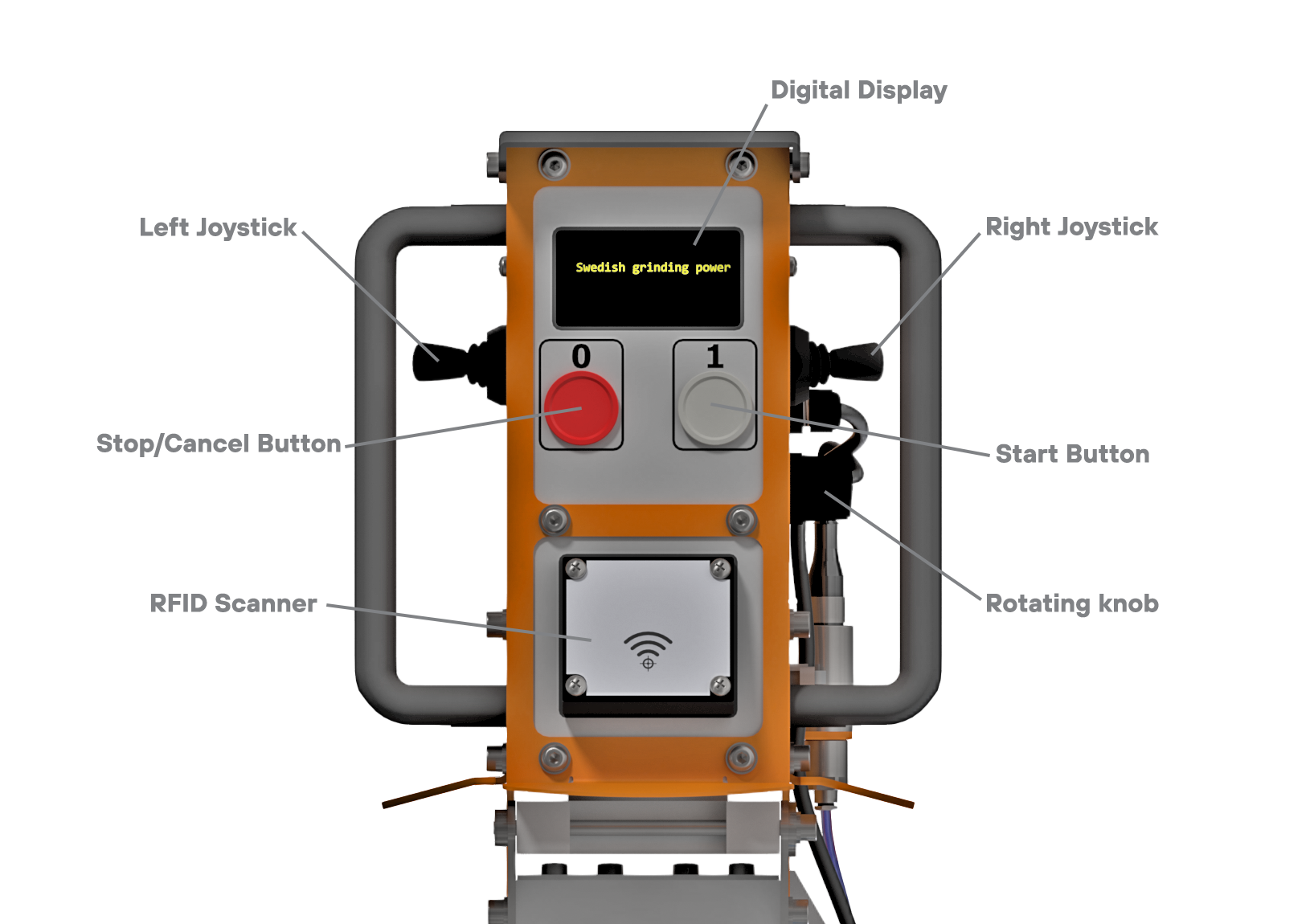
There are a several controls on the sharpening head that are used to operate your XR28™.
They are:
Digital Display
Left Joystick
Right Joystick
Rotating knob
Stop / Cancel operation
Start / Enter operation
RFID Scanner
Each one has a specific function, with some having multiple functionality depending on the state the machine is in.
1. Digital DisplayThe Digital Display provides the user with information required to understand what state the machine is in and how to proceed.
|
 |
2. Left JoystickThe left joystick can be toggled up/down/forward/backward. By following the instructions as displayed on the digital display it will indicate in which direction the joystick should be toggled. Standard on all XR28™ machines is the '2Hand Start' functionality. This requires the left joystick to be toggled down while pressing the start button. The left joystick is also used to toggle between the 'TIME' and 'EXTRA TIME' functionality. |
3. Right JoystickThe right joystick is the most versatile controller. In the machine ideal state the right joystick is used to move the arm up and down. By toggling the right joystick backward you enter the machine MENU. In the machine MENU the right joystick is used to navigate between different settings/controls. |
4. Rotating KnobThe rotating knob is used to adjust the TIME parameter while the machine is in an idle state. When the sharpener is in the MENU state, the rotating knob can also be used to navigate and will be required to troubleshoot your XR28™ |
5. Stop / Cancel OperationThe [0] red stop or cancel button is used to stop the current sharpening cycle. While in the MENU state, the stop button can be used to cancel a function. |
6. Start / Enter OperationThe [1] start button is used to start the sharpening cycle. While in the MENU state, the start button will also be used to select functions. |
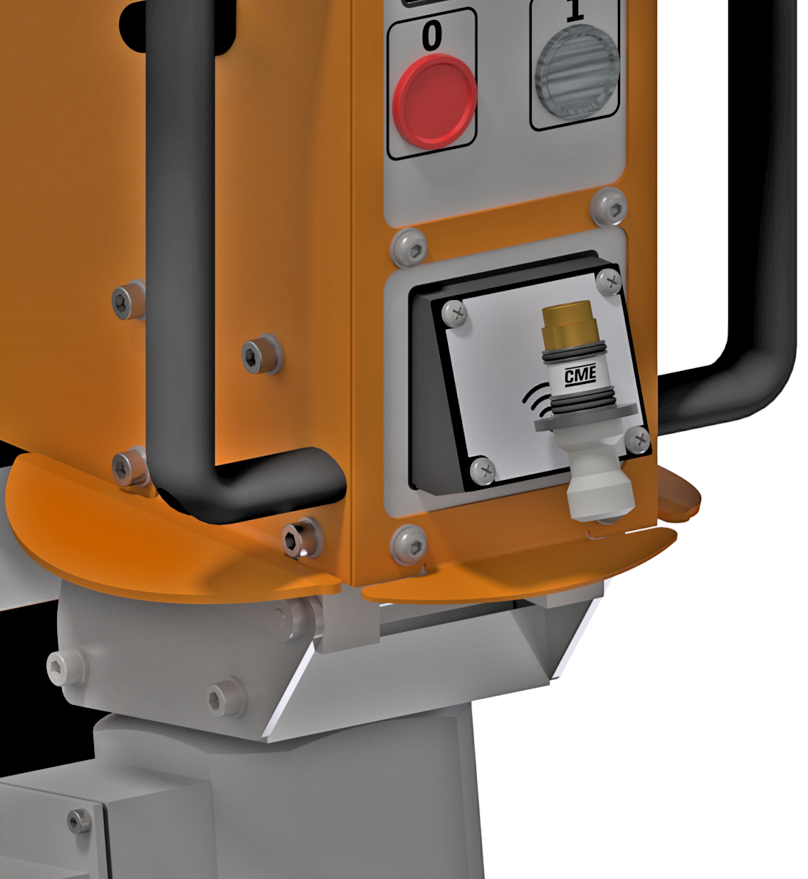
7. RFID ScannerThe RFID Scanner is used to scan the appropriate sharpening tool. This will let your XR28™ know what size and profile you intend to sharpen and load the appropriate settings. |
Digital Display
Understanding the digital displa.
|
WIFI: In the top right hand corner of the display, you will notice the WiFi connectivity and strength of signal. It will display on of three options: "I" = connected to your network, however no internet connection "C" = connected to server for synchronisation No symbol = not wifi network connected. |
|
|
TIME: This display indicates the length of the sharpening cycle in seconds. You use the rotating knob to increase or decrease the time. When toggling the left joystick up you switch to "EXTRA TIME". This function should be used when the button requires a little bit of extra sharpening after the initial cycle. |
 |
|
SIZE: The size and profile is registered when you scan your sharpening tool |
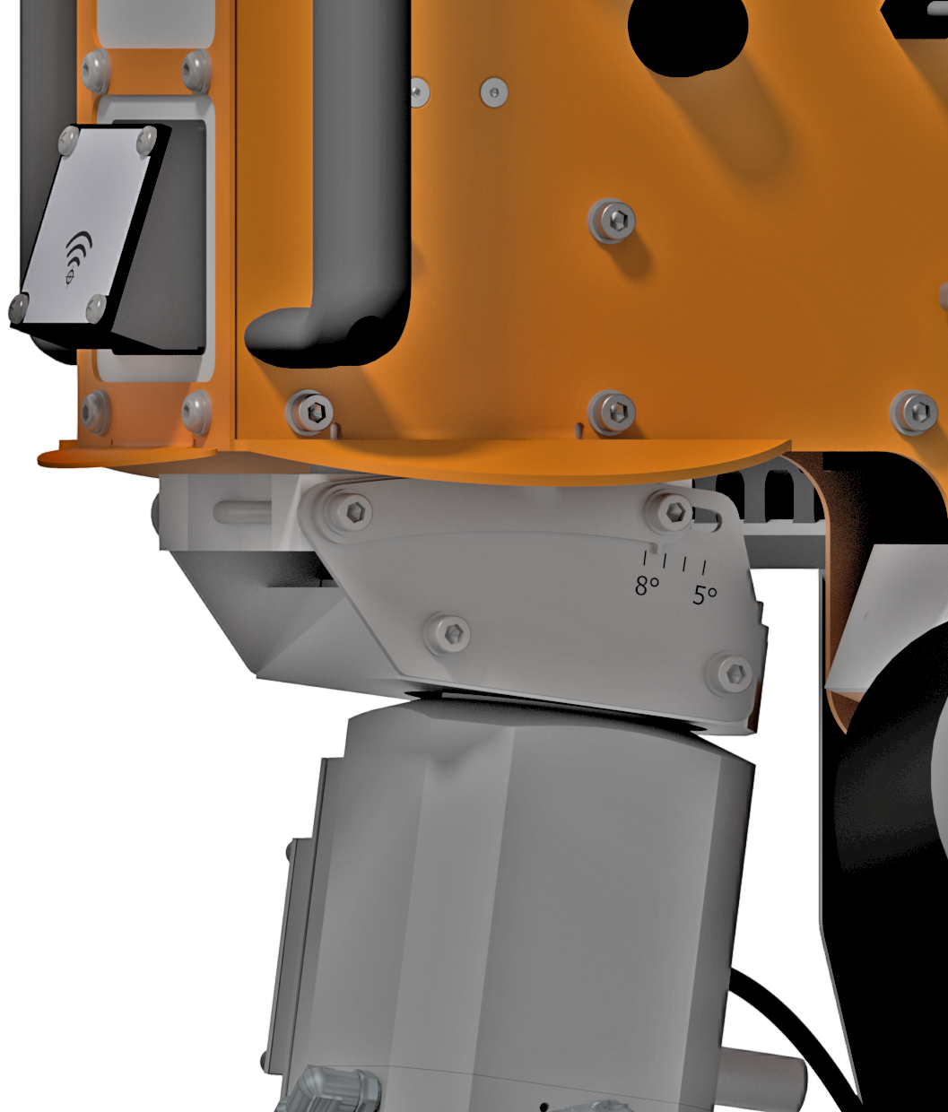
Set orbital rotation angle
|
It is important to set the orbital rotation angle to the correct angle to keep the designed shape of the sharpening tool. The recommended rotation angle is 7-7.5 degrees for all button profiles with a normal wear flat, 30% - 50%. A smaller rotation angle (5% - 6%) will cause the designed shape of the tool to deepen and could cause nipple formation on the button. A larger rotation angle will flatten the profile and may induce vibrations. |
 |
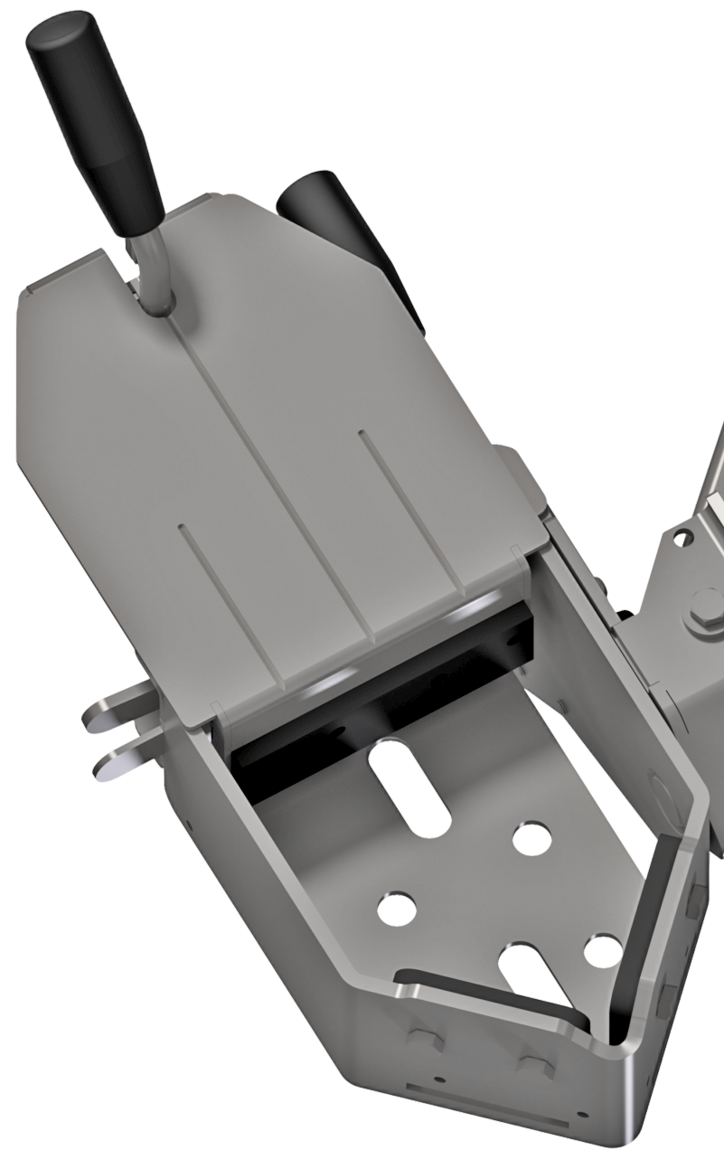
Inserting and Clamping drill bit
The XR28™ is equipped with the patented bit table that allows for comfortable maneuverability, stability during sharpening, quick adjustments and easy clamping.
The fastest way to get familiar with the bit table is by using it. There are a few steps to get you started.
|
Firstly, the bit table is released by lifting the locking hook at the bottom of the body, as can be seen in the image. This will allow the bit table to move freely in the x-y plane. |
 |
|
The bit table has a macro adjustments and quick clamp function. With the clamping lever in the upright position, the macro adjustments can be made by squeezing together the macro adjustment levers on the side of the bit table and then moving the clamping section backward or foward as required. |
|
|
The bit table is designed to be used for both smaller, top hammer bits and bigger DTH bits. For the smaller bits, the bottom plate and the multi bit holder is used, both are standard accessories included with every machine. For larger bits, such as DTH bits with a long shank, the bottom plate can be removed. This is easiest done when the macro adjustment is all the way open. |
 |
|
With the desired setup in place, you can now load the drill bit you wish to sharpen. Once the drill bit has been loaded into the bit table, use the macro adjustment lever and push the table against the drill bit. You can now use the quick clamping function by pulling the clamping lever down into the a horizontal position. When you rotate the bit to sharpen the gauge buttons, you can simply release the quick clamp, rotate the bit and then re-clamp the bit. |
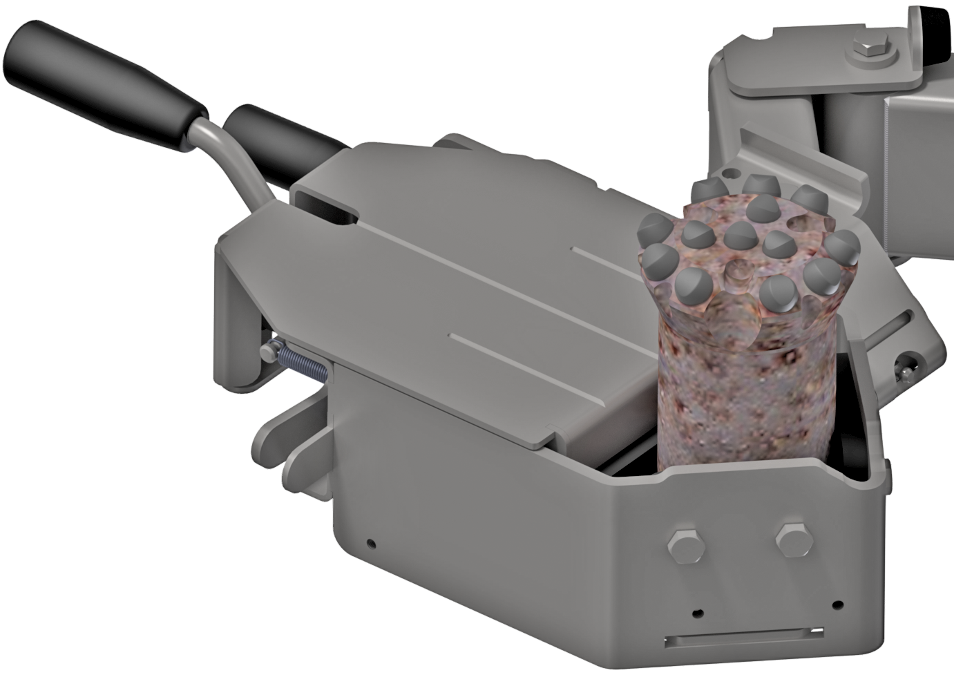 |
The bit table is now loaded with a bit and ready to be sharpened. The angle of the bit table will need to change when sharpening gauge buttons, or any buttons on an angle.
How to set the tilt angle is discussed in the next section below.
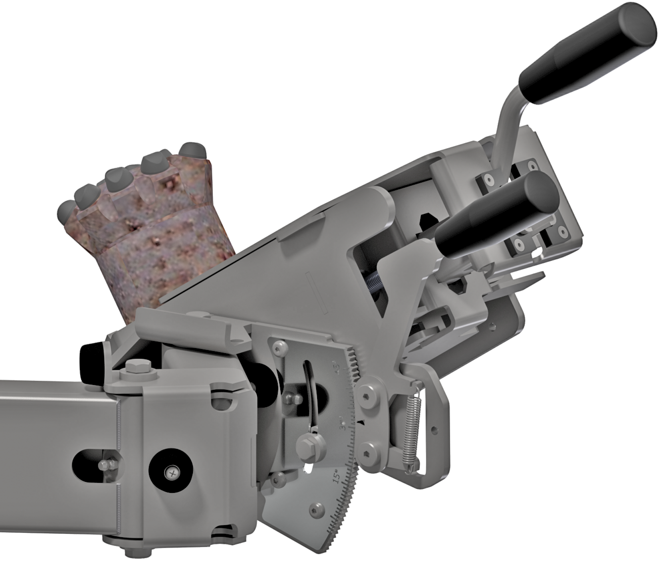
Setting tilt angle
In its default horizontal position the bit table is at 0 degrees. This is appropriate when sharpening face buttons.
When sharpening gauge buttons, the bit table needs to be tilted to the same angle as the button. You can get this information from the bit manufacturer.
|
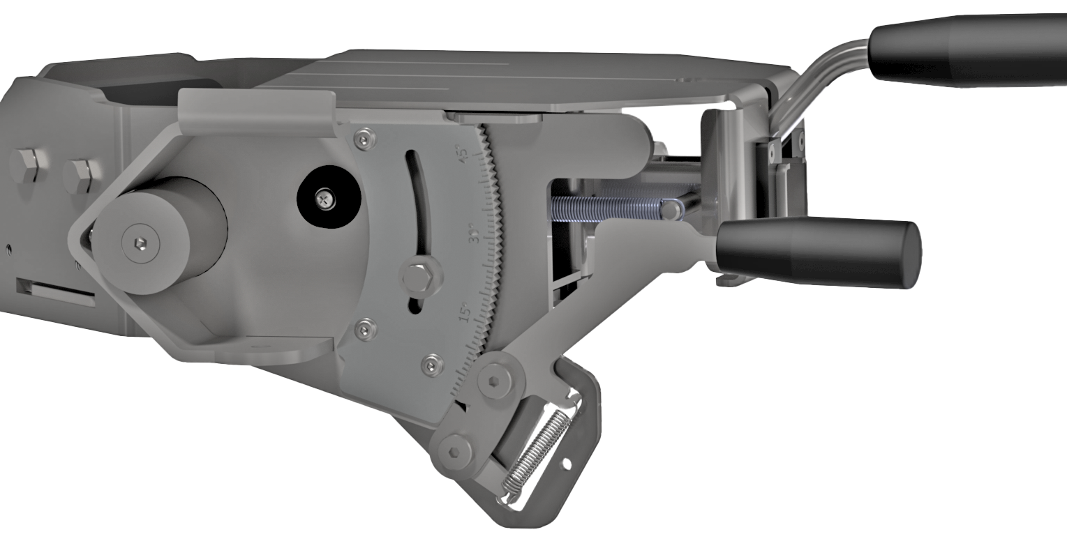
To adjust the tilt of the bit table, you lift up the tilting lever which releases the tilt lock. While holding the tilting lever up adjust the angle of the bit table to your desired angle and release the lever to lock the tilt. |
 |
|
The desired tilt angle can be 'pre-set' by adjusting the bolt on the side of the bit table. Loosen the bolt slightly, move it to your required angle, then tighten the bolt in place. Now when you adjust the tilt of the bit table, the maximum tilt will be where you set the bolt. This will make it easier to switch between title angles when sharpening many of the same bits. |
 |
NOTE: It is often easier to load/unload bits from the bit table when it is at an angle.
Selecting sharpening cup and profile
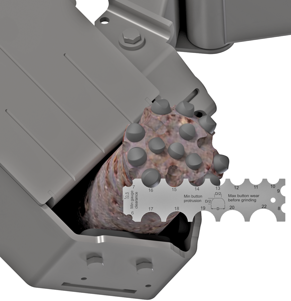
It is important to use the correct sharpening tool for each different type of bit / button you are sharpening. To find the correct tool, you will need to know the size of the button and the profile of the button.
|
The size can easily be determined by using the measuring CME measuring tool included with every machine. Simply hold the tool against the base of the button and see which one fits. NOTE: these sizes are in milimeter (mm). |
 |
|
The profile of the button needs to be provided by the bit manufacturer. There are four (4) common profiles used, they are:
|
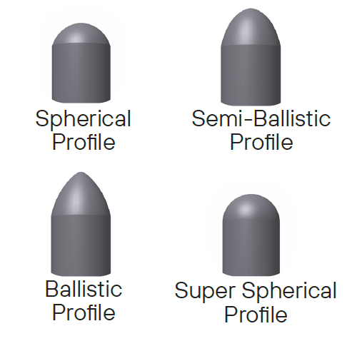 |
|
With the size and profile determined, you find the correct sharpening tool and scan it by holding it close to the RFID Scanner. The machine will signal that it has scanned the sharpening tool by switching the lights off and on again and the scanned tool will display in the digital display. |
 |
Setting grinding time
The final step before your first sharpening cycle can begin is to set the cycle time.
|
Using the rotating knob, you will adjust the cycle time. To determine how long your sharpening cycle should be is defined by a number of factors that need to be taken into consideration.
Experience will be the best teacher to find the best cycle times. |
 |
|
After completion of the inital cycle, you would inspect the button. Should a few more seconds of sharpening be required, you can toggle the left joystick up to activate 'EXTRA Time'. The built-in sharpening cycle settings for EXTRA time are different to normal time. EXTRA Time was specifically designed to finish off the button sharpening and should not be used as the norm. |
|
NOTE: Inspecting the sharpened button is an important part of the sharpening process. This will be discussed in greater detail on the next page.
Please use the arrows at the top to proceed to the next section.